Grupo 03 - Smart Thermal Chamber for Automated Testing System Production
![[Vídeo do projeto]](/projects/Group03/Chamber.png)
| Team: |
Grupo 03: Bernardo Dominguez (Coord.) , Bruno Figueiredo , Laura Villalba , Sara Reis , Simão Pinto |
| Company: | PICadvanced S.A. |
| Supervisors: |
Osvaldo Pacheco (DETI)
Ricardo Ferreira (PICadvanced S.A.) Francisco Rodrigues (PICadvanced S.A.) |
PICadvanced is dedicated to the development of optoelectronic transceivers for fiber-to-the-home networks, standing out for its innovation and development of high-speed transceivers such as 10Gbps, 25Gbps, and more recently 50Gbps. To ensure product validation and guarantee full functionality under all conditions, it is crucial that the transceivers operate reliably in ambient temperatures of up to 70°C. This project consists of elaborating a small thermal chamber to ensure the reliability and performance of optoelectronic transceivers under different temperature conditions. This thermal chamber is programmed to actively control the internal temperature, heating or cooling as needed for the test. During testing, processed data is collected and displayed on the computer through a Graphical User Interface (GUI).
Challenge
PICadvanced is a Portuguese technology company specializing in the development of innovative solutions for the telecommunications industry, particularly in the field of optical communication systems, offering innovative and cost-effective solutions. To achieve this, it uses optical components and transceivers, merging two major fields: electronics and optics.
For these validations, PICadvanced requires the development of a small intelligent test oven capable of heating and cooling the ambient temperature, controlling it, and enabling the automatic collection of data from the test boards already developed through software.
The proposed problem revolves around ensuring the reliability and performance of 10Gbps SFP+ optoelectronic transceivers under different temperature conditions, ranging from 0°C to 70°C. For these validations, an intelligent thermal chamber was developed, capable of simulating and withstanding both heating and cooling processes.
The temperature-controlled environment is important for validating the functionality of the client’s product. Its small dimensions are intentionally designed to allow easy transportation of the project and make the testing process more practical.
PICadvanced already owns industrial-scale thermal chambers for more complex tests, therefore, the challenge for this proposal emerged from the need for something simple, practical, and functional.
In summary, our challenge can be explained as follows: the construction of a small thermal chamber, integrated with the heating/cooling system; a circuit for processing the data collected by the temperature and humidity sensors, and processing this data through a microcontroller. All the collected data, including the results of the transceiver tests, are displayed to the client via the GUI.
Results
The following figure represents a high-level block diagram that will be used to provide a clearer and more specific explanation of the system being developed:
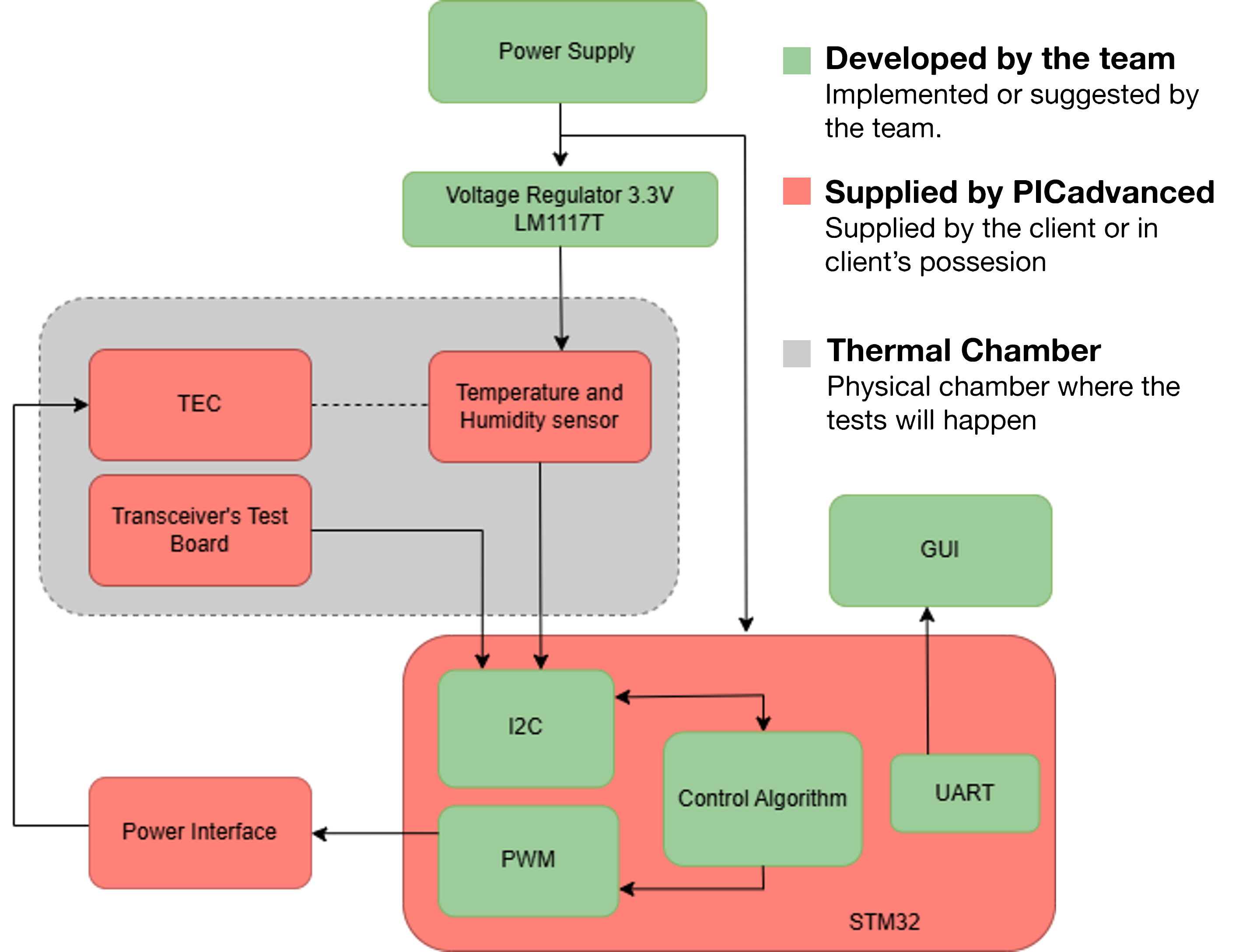
Thermal Chamber: The materials used to construct the thermal chamber are stainless-steel sheets, and the insulation will be made of rockwool.
The thermal chamber will have the following features:
-
A stable and secure base to prevent unnecessary accidents.
-
The optical transceiver test board has reduced dimensions, which eliminates the need for a large thermal chamber.
Temperature and humidity sensor: During the cooling cycle, there is a possibility that condensation may occur inside the thermal chamber, turning the moisture into water. One of the first signs of this process will be the appearance of droplets on the chamber walls. To prevent this, a temperature and humidity sensor will be used to measure the air temperature and humidity. When the sensor reaches a critical level, an alarm/warning will be triggered to alert about this risk, thus protecting the transceivers and the electronic components.
Transceiver’s board: The test board supplied by the company holds in memory storage the values of the transceivers’ temperature and other important information that gives information about the performance of the transceivers during the test.
Heating/Cooling System: The Thermoelectric Cooler (TEC) is composed of semiconductors that transfer heat from one plate to another based on the Peltier effect, allowing for the heating and cooling of the thermal chamber.
This device is integrated into one of the walls of the thermal chamber and is controlled by a PID controller based on the information provided by the data collection system.
Graphical User Interface: All the collected data is displayed on a GUI that can be accessed through the computer. The information displayed includes the measured temperature and humidity, test result data, and alarms triggered if critical conditions that could affect the tests are reached.
Users can interact with the chamber through this GUI, which allows for:
-
Adjustable setpoint temperature.
-
Customizable sampling frequency for test data.
-
The ability to cancel tests in case of emergency or error.
-
The system will provide real-time feedback, allowing the user to adjust the configuration as needed.
Thermal Chamber
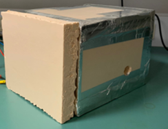
The presented intelligent thermal chamber is a compact and efficient solution specifically designed to test the performance of optical transceivers under various ambient temperature conditions. This equipment is essential for validating the functionality of transceivers across critical temperature ranges, ensuring their reliability between 0 and 70 degrees Celsius.
Inside the chamber, a test board is installed to house the transceiver under evaluation. The internal environment is monitored by a temperature and humidity sensor, ensuring parameter stability and enabling the detection of variations that could compromise the results.
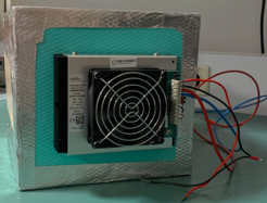
A thermoelectric cooler, strategically positioned on one of the chamber’s internal walls, plays a key role in thermal control. This component employs Peltier technology to efficiently heat or cool the internal environment, allowing the desired temperature to be reached quickly and maintained with precision.
To minimize thermal losses, the chamber is constructed with insulating material, ensuring high energy efficiency and maintaining stable conditions during tests. Additionally, a sealed aperture allows the passage of cables needed for powering and communicating with the transceiver without compromising thermal insulation.
The design includes an insulating door, facilitating access to the chamber’s interior for component installation or removal. The electronic boards are arranged on a dedicated support, ensuring that the internal walls remain unobstructed. This configuration prevents condensation formation, which could impair component performance or interfere with test results.
Thanks to its optimized design and precise control, this intelligent thermal chamber delivers reliable results, enabling optical transceivers to be tested under real operating conditions.
Transceiver’s board
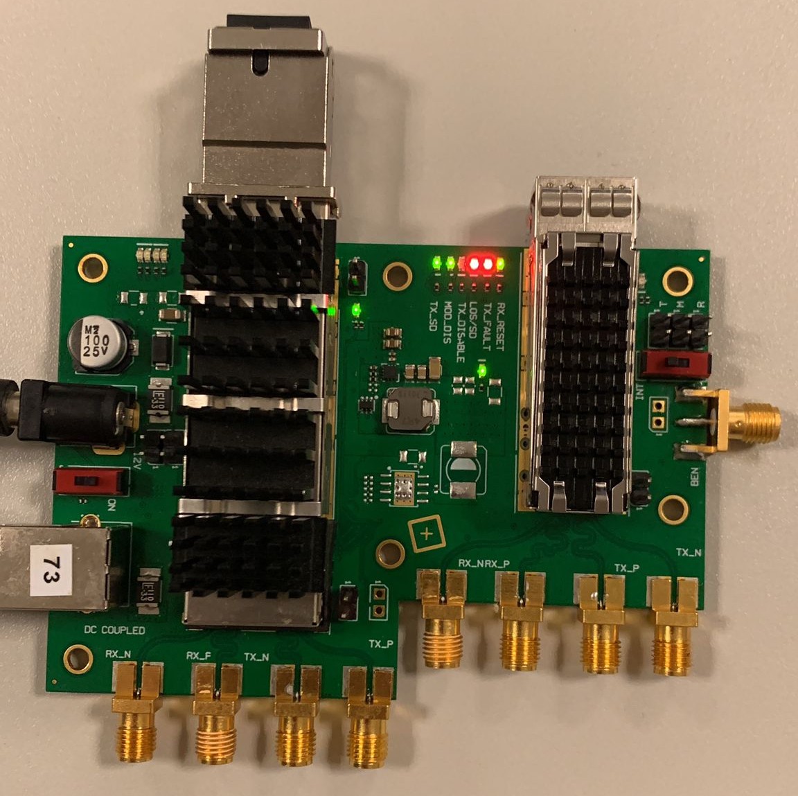
The test board for the optical transceiver facilitates the collection and monitoring of real-time data, ensuring the device’s functionality and performance under various conditions.
This board includes a direct connection interface with the transceiver, enabling its simple and efficient integration into the testing system. Communication between the test board and the microcontroller is carried out via the I2C protocol, ensuring reliable and efficient data exchange.
The transceiver features an integrated temperature sensor that measures its own temperature. This sensor is essential as the transceiver generates heat during operation, resulting in a temperature that may slightly differ from the ambient temperature controlled by the thermal chamber.
The test board also provides an array of memory addresses that stores various critical information about the transceiver. The key data collected includes:
- Transceiver temperature: monitored by the integrated sensor.
- Transmission power (Tx Power): indicates the strength of the emitted optical signal.
- Reception power (Rx Power): reports the strength of the received optical signal.
- Supply voltage: must be maintained at 3.3V to ensure optimal transceiver operation.
Accessing this information is achieved by querying specific addresses in the memory array provided by the test board. Data collection occurs in real-time, enabling continuous analysis of operational conditions and immediate identification of any deviations from expected parameters.
This advanced setup allows the test board, in conjunction with the microcontroller and the thermal chamber, to form a complete and integrated solution for evaluating the performance of optical transceivers under various operating conditions.
Graphical User Interface
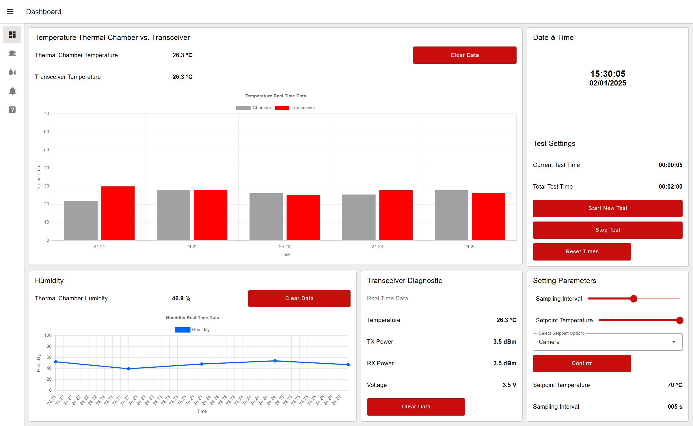
The developed dashboard is an interactive and intuitive interface that allows users to monitor and control the system, providing a detailed view of the performance and behavior of the components in real-time.
Main Menu
In the main menu, users have access to several essential features:
- Temperature Graph: Compares the current temperature of the thermal chamber with that of the transceiver, providing a clear view of the difference between the ambient temperature and the one generated by the device.
- Humidity Graph: Displays real-time humidity values, ensuring that the environment inside the thermal chamber is within appropriate limits.
- Transceiver Data: Presents detailed information, including temperature, transmit power (Tx Power), receive power (Rx Power), and supply voltage.
- Test Stopwatch: Displays the times of the tests currently in progress, allowing precise tracking of the progress.
- Setpoint and Sampling Definition: Allows the user to enter a setpoint, choosing whether it is the chamber’s temperature or the transceiver’s temperature that should reach that value. Additionally, the sampling interval can be configured, determining how frequently the data will be updated.
Other Windows
Detailed Graphs: A window dedicated to presenting comprehensive graphs of all the temperature and humidity information of the chamber over time, allowing detailed historical analysis.
Transceiver Evolution: A section focused on the evolution of the transceiver’s parameters, such as power and temperature, throughout the testing period.
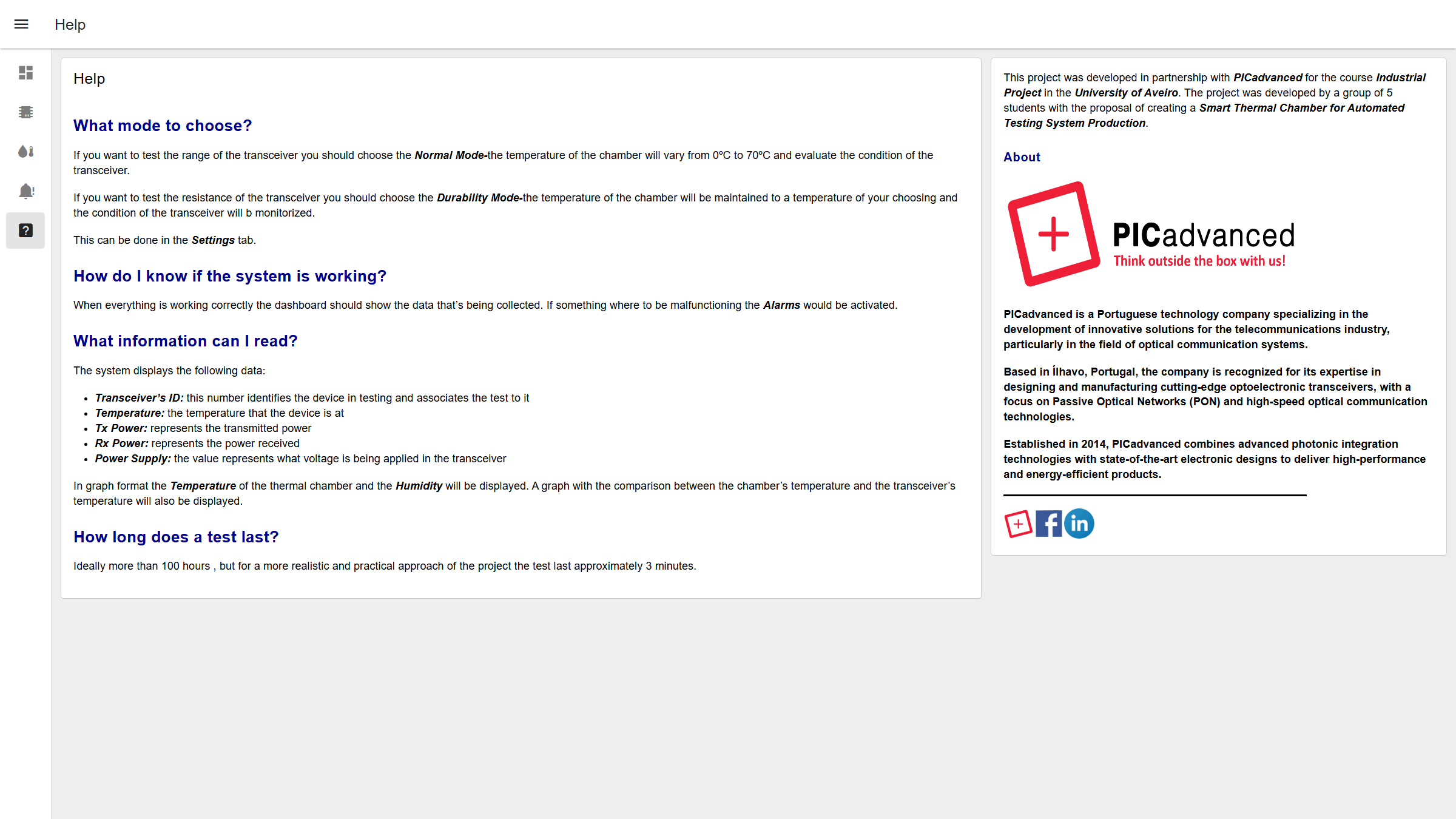
Help and Information
The dashboard includes a help tab where users can find clear instructions on how to operate the system. Additionally, there is information about the development team and the partner company, highlighting the professionalism and collaboration involved in the project.
Alert Functionality
The system is equipped with an alert functionality. Whenever operating conditions are not ideal, such as in cases of elevated humidity, the dashboard immediately notifies the user, allowing for prompt corrective actions.
More information
Key Milestones
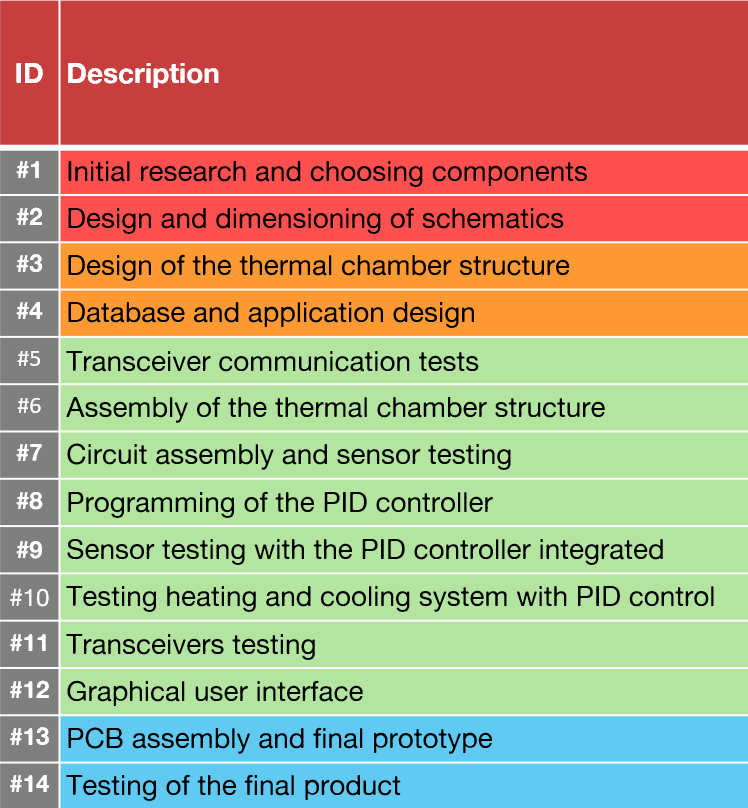
The red represents the Inception Phase. The orange represents the Elaboration Phase. The green represents the Construction Phase. The blue represents the Transition Phase.
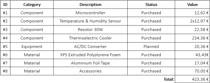
Financial status